
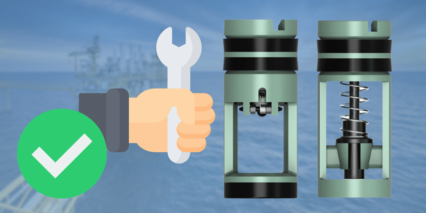
A drill pipe float valve is a downhole non-return valve that stops fluid from flowing back up the drill string during connections. Size it to your tool joint using the specification chart below - models run from 1R (1-21/32" diameter) up to 6F (5-11/16" diameter). Install it with the top of the valve facing up in the string, lubricate the side seals with hydraulic oil, and rotate slightly while inserting to avoid seal damage. Keystone is the first float valve manufacturer certified to API Spec 7V across all F and G series models.
A drill pipe float valve keeps drilling fluid moving in one direction only. Also known as a non-return valve, this type of down hole valve prevents undesirable fluids from backing up into the drill string any time the drilling crew is making or breaking connections.
That's why selecting and installing the right Drill Pipe Float Valves matters. And in the oil and gas industry, where safety is key, one wrong move can lead to disaster.
But don't stress about it, we've got the perfectly engineered Drill Pipe Float Valve size chart and installation steps for you.
- What is a Drill Pipe Float Valve?
- How are Drill Pipe Float Valves installed?
- Tool Joint Specification Chart
- Drill Pipe Float Valve Size Chart
- The Keystone Energy Drill Pipe Float Valves
- Frequently Asked Questions
A drill pipe float valve is a downhole check valve installed inside a float sub, drilled-out drill collar, or bit sub that allows drilling fluid to flow down the drill string but blocks it from flowing back up.
Finding the best fit for every individual project is important, and the different types go beyond just the split between the F-type plunger valves and the G-type flapper valves.
What's the difference between Model F and Model G float valves?
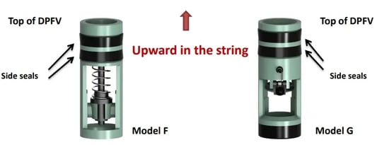
Model F is a plunger-style valve and Model G is a flapper-style valve. The plunger design uses a spring-loaded piston that seats against the valve body, while the flapper design uses a hinged plate that swings closed against back pressure. Model F are available in every size from 1R through 6F. Models G cover sizes 1F-2R through 5F-6R, and Models GC cover 2F-3R through 5F-6R.
How are Drill Pipe Float Valves installed?
Installing a drill pipe float valve takes three steps: size the valve to the tool joint, clean and inspect the bore, then lubricate the side seals and rotate the valve in. The whole operation runs a few minutes per valve. The single mistake that ruins it is orientation - the top of the valve has to face up in the string, or the valve blocks flow in the wrong direction.
Drill Pipe Float Valves are easily installed by following these steps:
- Determine the size of the Drill Pipe Float Valve (DPFV) to be installed according to the size and type of connection they are being installed into. Refer to the Tool Joint specification chart below.
- Visually inspect the bore of the float sub or drilled out drill collar, and bit sub for shavings and/or foreign objects that could damage the seals of the DPFV. Next, clean out the bore as needed.
- Lubricate the side seals of the DPFV using hydraulic oil and insert the valve into the bore of the float sub (or the drilled out drill collar) - to do so, rotate the DPFV slightly while inserting, this will lessen the force required and the chances of damaging the side seals.
*Caution must be taken to ensure that the DPFV is always installed with the top of the valve facing upward in the string.
Tool Joint Specification Chart
Use this chart to match your tool joint type and connection size to the correct float valve model. Find your connection type in the left column, read across to your connection size, then read up to the model size header. That model number - 1R, 2F-3R, 4F, and so on - is what you order and what you look up in the size chart below.
The chart covers 15 tool joint types across 10 model sizes, from 2-3/8" connections up to 8-5/8". If you're working with API Regular, API Full Hole, API Internal Flush, Hydril, Hughes, Reed, or Union Tool connections, your size is here.
|
TOOL JOINT TYPES |
MODEL SIZES |
|||||||||
|
1R |
1F-2R |
2F-3R |
3F |
3.5IF |
4R |
4F |
5R |
5F-6R |
6F |
|
|
API REGULAR |
2-3/8" |
2-7/8" |
3-1/2" |
4-1/2" |
5-1/2 |
6-5/8 |
8-5/8" |
|||
|
HUGHES OR REED ACME |
2-3/8" |
2-7/8" |
3-1/2" |
4-1/2" |
5-1/2 |
6-5/8" |
||||
|
UNION TOOL |
2-3/8" |
2-7/8 |
4-1/2" |
5-1/2 |
6-5/8"✝ |
|||||
|
HUGHES OR REED DOUBLE STREAM- LINE |
2-7/8" |
3-1/2" |
4" |
5" |
5-1/2 |
|||||
|
API FULL HOLE |
2-3/8" |
2-7/8" |
3-1/2" |
4" |
4-1/2" |
4-1/2"* |
6-5/8"* |
|||
|
REED ACME FULL HOLE |
3-1/2"* |
4-1/2"* |
5-1/2 |
|||||||
|
HUGHES ACME STREAMLINE |
2-3/8" |
2-7/8" |
3-1/2" * |
4-1/2"* |
5-1/2 |
|||||
|
HUGHES XTRA HOLE |
2-7/8" |
3-1/2" |
4-1/2" |
5" |
5-1/2" |
|||||
|
REED SEMI-INTERNAL FLUSH |
2-7/8" |
3-1/2" |
4-1/2" |
5" |
||||||
|
API INTERNAL FLUSH |
2-3/8" |
2-7/8" |
3-1/2" |
4" |
4-1/2"* |
|||||
|
HYDRIL TYPE IF(INT .FLUSH EXT. UP- SET) |
2-3/8"* |
2-7/8"* |
3-1/2"* |
4-1/2" |
5" |
|||||
|
HYDRIL EIU |
3-1/2" |
4" |
4-1/2" |
5-1/2" |
6-5/8" |
|||||
|
HYDRIL TYPE F |
2-7/8" |
4-1/2" |
5-1/2" |
6-5/8" |
||||||
|
HUGHES EXT. FLUSH ACME |
3-1/2" |
4-1/2" |
5-1/2" |
6-5/8" |
||||||
|
HUGHES EXT. FLUSH FULL HOLE |
4-1/2" |
|||||||||
|
* Indicates that the float subs id these sizes have a smaller ID. ✝ Indicates interchangeability. Models G and GA, are available in sizes |
||||||||||
|
1F-2R thru 5F-6R. Models GC and GCA are available in sizes 2F-3R thru 5F-6R. Models F and FA are available in all sizes. Model FC is available in sizes 2F-3R thru 6F. |
||||||||||
Drill Pipe Float Valve Size Chart
The size chart below gives you five dimensions for each valve model: outside diameter (D), the recess diameter the sub needs (R), valve length (L), baffle plate recess diameter (T), and the valve inside diameter for both Model F and Model G. Valve outside diameters run from 1-21/32" on the 1R up to 5-11/16" on the 6F. Lengths run from 5-7/8" to 14-5/8".
Two rules govern how these numbers get used. The recess diameter is always the valve diameter plus 1/32" - that clearance is what lets the valve seat without binding the side seals. And the total bore depth you need is given by the formula below, which accounts for the valve, the pin, and a quarter inch of working room.
Refer to the following diagrams for dimensions and sizing details.
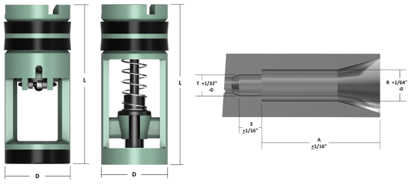
A = L (Length of Float Valve) + Length of Tool Joint Pin + 1/4” Clearance
|
Valve Size
|
D
Diameter of Valve
|
R
(D + 1/32")
Diameter Recess F/ Valve
|
L
Valve Length
|
T*
Baffle Plate
Recess Diameter
|
**Valve I.D. Model F
|
**Valve I.D. Model G
|
|
1R
|
1-21/32"
|
1-11/16"
|
5-7/8"
|
1-5/16"
|
1"
|
N/A
|
|
1F-2R
|
1-29/32"
|
1-15/16"
|
6-1/4"
|
1-1/2"
|
1-1/4"
|
1"
|
|
2F-3R
|
2-13/32"
|
2-7/16"
|
6-1/2"
|
1-29/32"
|
1-9/16"
|
1-1/4"
|
|
3F
|
2-13/16"
|
2-27/32"
|
10"
|
2-7/16"
|
1-7/8"
|
1-5/8"
|
|
3.5IF
|
3-1/8"
|
3-5/32"
|
10"
|
2-11/16"
|
1-7/8"
|
1-5/8"
|
|
4R
|
3-15/32"
|
3-1/2"
|
8-5/16"
|
2-15/16"
|
2-5/16"
|
1-31/32"
|
|
4F
|
3-21/32"
|
3-11/16"
|
12"
|
3-1/4"
|
2-1/2"
|
2-3/16"
|
|
5R
|
3-7/8"
|
3-29/32"
|
9-3/4"
|
3-3/8"
|
2-3/4"
|
2-1/4"
|
|
5F-6R
|
4-25/32"
|
4-13/16"
|
11-3/4"
|
4-9/32"
|
3-1/4"
|
2-7/8"
|
|
6F
|
5-11/16"
|
5-23/32"
|
14-5/8"
|
5-3/16"
|
4-1/8"
|
N/A
|
|
* Disregard if this diameter is the same or smaller than the standard tool joint I.D.
|
||||||
|
** All 10M Model F valve I.D.s are 1/8” reduced and all 10M Model G valves I.D.s are 7/32” reduced then listed above.**
|
||||||
Quick reference: valve size at a glance
|
If your valve model is...
|
Outside diameter
|
Valve length
|
Model F I.D.
|
|
Small (1R, 1F-2R)
|
Under 2"
|
Under 6-1/4"
|
1" to 1-1/4"
|
|
Mid-range (2F-3R, 3F, 3.5IF)
|
2-13/32" to 3-1/8"
|
6-1/2" to 10"
|
1-9/16" to 1-7/8"
|
|
Large (4R, 4F, 5R)
|
3-15/32" to 3-7/8"
|
8-5/16" to 12"
|
2-5/16" to 2-3/4"
|
|
Largest (5F-6R, 6F)
|
4-25/32" to 5-11/16"
|
11-3/4" to 14-5/8"
|
3-1/4" to 4-1/8"
|
How do you calculate float sub bore depth?
Add the valve length (L) from the size chart, the length of the tool joint pin, and 1/4" of clearance. That total is dimension A on the diagram above. A float sub is a short section of pipe machined with an internal recess that holds the float valve in the string. Run the calculation before machining a sub or drilling out a collar - a bore that's short by even a fraction leaves the valve proud of the shoulder, and the connection won't make up correctly.
The Keystone Energy Drill Pipe Float Valves
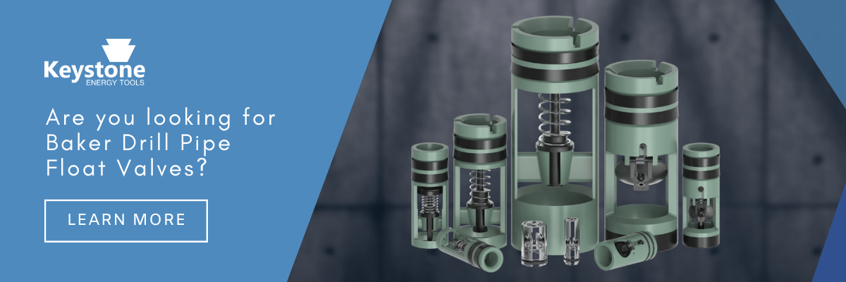
Keystone manufactures drill pipe float valves with upgraded spring materials, full serial-number traceability, and certifications on every valve. All models are interchangeable with Baker® Style Model F and Model G valves, along with the matching baffle plates and valve pullers.
Keystone valves come with certifications (traceability).
Keystone started stenciling each float valve with an independent serial number and a work order so we can trace the origin.
Other Benefits of Keystone Drill Pipe Float Valves
Other benefits of Keystone Float Valves:
- All Flappers are investment cast and then case-hardened for wear resistance.
- Elastomers available are Nitrile Butadiene (NBR /Buna N) and Viton® (Fluoroelastomer / FKM).
- All KET Float Valves, baffle plates, and valve pullers are interchangeable with the Baker® Style Model F, and Baker® Style Model G Float Valves.
- High- and Low-pressure test charts available upon request at placement of order.
Keystone's Full Line of Float Valves
At Keystone, we recognize the severity of drilling with a reliable and trusted valve - float valves are essential for drilling and must stand the test of harsh environments. When safety is of the utmost importance, you need a valve that you can trust.
Keystone Energy Tools is now the first drill pipe float valve manufacturer in the world certified to API Spec 7V, covering all G and F series models. If you spec, source, or run drill pipe float valves, you can now require API Spec 7V certification on your purchase orders and verify it through API's Composite List.
If you're looking for a trusted supplier of float valves that can stand up to the rigors of your drilling operations, Keystone has you covered. See our full range of float valves and find out how they can improve your drilling efficiency and safety.
Finding the best fit for every individual project is important, and the different types of drill pipe float valves go beyond just the split between the F-type plunger valves and the G-type flapper valves.
Learn more about our line of Drill Pipe Float Valves today.
FAQs
Related reading: Classification and Types of Drilling Pipe · API Spec 8C: Drilling and Production Hoisting Equipment
About Keystone Energy Tools
 Keystone Energy Tools is a manufacturer with over fifty years of combined experience in designing, manufacturing, and delivering high-quality oilfield tools, including elevators, slips, dies and inserts, tongs dies,safety clamps, stabbing guides, drill pipefloat valves, baffle plates, float valve pullers, rotating mouseholes, and tong blocks.
By using the latest in 3D modeling for product design and by staying current with the rapid advances in manufacturing technology and quality-assurance standards, Keystone is able to manufacture and produce the most reliable products on the market today. All Keystone Handling Tools are manufactured according to API 8C and API 7K Standards.